GENERAL FEATURES
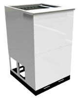
Loads are built in cabinets of galvanized sheet metal or powder coated, suitable for outdoor installation, with resistors made in stainless steel and cooled by forced ventilation and low losses tropicalized inductors.
An efficient heat dissipation is a very important factor to get the steadiness of load, since the power absorbtion of resistors decreases with the increasing of temperature. The cooling fans installed in our equipments are characterized by a plentiful airflow in order to reduce the thermal drift of resistors, so the load power is mantained stable even over long duration test sessions.
When load power is fully disconnected, the fan stop is delayed, to ensure a more gradual cooling of resistors and extend their working life.
The load banks are conceived to be modular, so it is possible to combine several loads together to achieve the necessary power, or add later other load banks to enlarge a configuration already existing.
Standard voltages: 48 VDC, 60 VDC, 120 VDC, 240 VDC, 440 VDC.
Safety Outfitting
| Fault type |
Protective device | Protective device consequence |
|
Resistors short circuit |
A properly sized fuse for each load step | Reduction of active power |
|
Resistors overload |
Unnecessary | -- |
| Partial airflow lack |
Thermal protection switch | Instantaneous disconnection of the whole power |
| Full airflow lack (optional) |
Differential pressure switch |
Instantaneous disconnection of the whole power |
| Fans overload or short circuit | Adjustable motor protection circuit breaker |
Instantaneous fan stop Instantaneous disconnection of the whole power |
| Emergency stop | Red push-button with rotary unlocking |
Instantaneous fan stop Instantaneous disconnection of the whole power |
| Intrusion alarm (optional) | Door microswitches on doors and sheet panels |
Instantaneous fan stop Instantaneous disconnection of the whole power |
| Injuries caused by direct contact with potentially dangerous mechanical parts |
Protection net in front of fan impeller Grids or protection nets on all dangerous accessible openings | Permanent upkeeping of safety distances from hazardous parts (barriers) |
-
Typical appliction area: discharge and efficiency tests on battery packs.
As example, see some possible configurations in the table below:
|
DC Voltage |
kW | Curr.(A) |
Dimensions (WxHxD,mm) |
Pow. steps |
| 48 VDC | 10* |
| 700x1350x825 | 6 |
|
48 VDC |
| 191^ |
700x1350x825 | 8 |
| 60 VDC | 15* |
|
700x1350x825 | 6 |
|
60 VDC | 191^ |
700x1350x825 | 8 | |
| 60 VDC | 31* |
|
700x2050x1370 | 5 |
|
120 VDC | 63* |
700x2050x1370 | 6 | |
| 120 VDC | 95* |
1150x2050x1370 | 7 | |
|
120 VDC | 384^ |
1150x2050x1370 | 10 | |
| 240 VDC | 191* |
1150x2050x1370 | 7 | |
|
240 VDC |
384^ |
1150x2050x1370 |
10 | |
| 440 VDC | 191* |
700x2050x1370 | 7 | |
|
440 VDC | 255* |
700x2050x1370 | 8 | |
| 440 VDC | 383* |
1150x2050x1370 | 9 |
*
Power scale with resolution equal to 1 kW
^
Power scale with resolution equal to 1 A
-
All specifications listed above are approximate and can be changed because of design improvements.