An electric load generating current harmonics is defined distorcing load.
Typical examples of non-linear, distorcing loads are the ones related to power electronics: diode rectifiers, inverters and UPS. The most common effects resulting from current harmonics generation are the overheating of the alternator powering the electrical system in which such harmonics are present and the consequent increasing of losses, both thermal and electric, in addition to a voltage regulation potentially unstable, unless the machine has specific design characteristics (sub-transient reactance X"d not too low).
These factors must be taken into account by oversizing the alternator properly.
A relatively simple way to generate current harmonics and check their effects on the tested machine (and therefore its correct sizing) is to use a resistive load powered by a three-phase uncontrolled rectifier (six-pulse rectifier), interposed between generator and the load itself.
Distorcing loads are generally used to test emergency machines of telecommunication systems or data centers, which contain many UPSs or similar power electronic devices and where a heavy steadiness of power supply is required at same time.
Referring to the picture below, the current absorbed by load through the rectifier follows exactly the voltage trend represented by the white continuous line.
The dashed coloured lines represent the three-phase voltages generated by alternator, on the rectifier input.
The non-sinusoidal course of the current drawn by load is the responsible of harmonics generation circulating through the system, according to the Fourier's theorem.
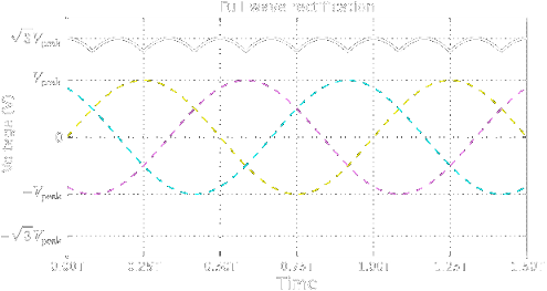
Picture from Wikipedia
We design these devices according to the technical specifications provided by customers. They can also be grouped with traditional resistive loads and thus assembled into the same cabinet, which will contain two well distinct power sections, each one with its respective commands, into a single module.
As example, we show in the table below the main features of an actually made load for military purposes, designed according to customer specifications, with an AC section of 252 kW power, splitted into 12 steps, in addition to a distorcing load section of 143 kW power, splitted into 9 steps. Total load power: 395 kW.
| Specification | Description |
|
Total power | 395 kW |
| Power supply | 400 VAC, 50 Hz - connection Yn |
| AC section power | 252 kW |
| Number of AC steps | 12 |
| Split of AC steps | 3x 180 W, 450 W, 1 kW, 2 kW, 4 kW, 8 kW, 16 kW, 32 kW, 64 kW, 125 kW |
| DC section power | 143 kW |
| Rectifier specifications | V in (max): 500 VAC V out (max): 670 VDC I out: 290 A Equipped with heat sink and cooling fan |
| Number of DC steps | 9 |
| Split of DC steps | 1 kW, 2 kW, 4 kW, 8 kW, 2x 16 kW, 3x 32 kW |
| Power connections | On copper bars |
| Protective devices | Fuses on each load step, thermal switch for partial airflow lack, thermal switch protection on rectifier, motor protection c.b. for main cooling fan. |
| Ventilation | Air, forced |
| Fan specifications | rated power 3 kW @400V-50 hZ, 1400 rpm, 26.000 m3/h, powered by external grid |
| Noise level | 79 dB(A) |
| Commands |
Local, by manual lever selctors fixed on the side wall of cabinet Digital net analyzer Serial communication for PC or PLC remote control |
| AUX power supply | 230 VAC from external grid |
|
Handling | By forklift or on wheels, pushed by hand |
|
Dimensions and weight | 1350x2050x1370 (WxHxD, mm), approx.750 kg |